This is going to be tedious stuff, but necessary knowledge if you don’t want your solar installation going up in smoke. The voltages of most solar/battery/inverter installations are relatively easy to manage, but the currents used are not. I’ve seen all kinds of errors in installations, even from supposed professionals. I am NOT a professional, so you can rely on me to make some dumbass errors of my own. What I’m writing is the result of my research. Before you take my word for something, confirm it for yourself.
Let’s start with fuses and breakers. Most of the fuses and breakers you can pick up at the local hardware store are a bad idea for large amounts DC power–especially the breakers. Remember that alternating current passes through a 0 voltage, 0 current point 60 times a second. If the circuit breaker trips and an arc forms between the contacts it’s going to last at most for about 1/60th of a second unless the voltage of the next alternation is so far above the rating of the breaker that it can reinitiate an arc along the ionization path. Breakers have arc-quenching structures inside them to minimize the damage of opening a circuit under full fault load, but AC breakers are designed to take advantage of the short period the arc will last even if the quenching doesn’t work immediately. That doesn’t happen with a DC breaker, so the arc can persist, melt all the guts and catch the housing on fire. That’s probably not what you had in mind. Some AC breakers have a DC rating, but unless you’re prepared to dig deep into breaker specs you should simply choose a properly rated DC breaker. Which will probably be about five times what an AC breaker costs. That’s a small price to pay for not turning into a crispy critter because a cheaper breaker popped and flamed out while you slept.
I’ve also discovered that Square-D makes a series of breakers called AO or AOB that are DC rated up to 125VDC. I haven’t tried these but the price is in the $20-30 range.
Fuses also have DC issues. A fuse with too short an air gap after the fuse wire vaporizes can also turn into an arc ball. Make sure you choose a fuse that is rated for the current and voltage you are trying to interrupt. Don’t assume a 50 amp 125VAC fuse will interrupt 50amps at 40VDC. It’s not uncommon to see a 125VAC rated fuse downrated to 32VDC. Don’t guess at this. For higher currents, like battery shorts, or failed inverter MOSFETS the fuse needs to be able to interrupt the maximum potential current the system could deliver. This is an issue on the battery side of the system, not so much on the panel and solar controller side. We’ll cover this a bit more later.
You should fuse each set of panels on the positive leg. If you are connecting panels in series you need one fuse appropriate to the current and voltage on the combined positive leg. Panels connected in series flow the same current as one panel–only the voltage increases. In the example of my six 310 watt panels, I combined each pair in series. A single 310-watt panel with an output voltage of 40 volts delivers 7.75 amps (amps = watts/volts). Two panels in series yield 80 volts and 620 watts, but it’s still 7.75 amps. I used 10 amp in-line fuses in my installation.
It’s common to use a combiner box to house the fuses and bring all the rooftop wires and connectors into two power leads that go into the cabin and to a solar controllers. No additional fuse is required between the solar controller and the combiner box since each leg is already fused. Since I’m using two solar controllers I connected my six panels as adjoining pairs in series with the resulting three positive wires and three negative wires going directly to the solar controllers. The MC4 connectors that are typically attached to solar panels leads make it easy to connect pairs in series. Just connect one panel’s male connector to the second panel’s female connector. the remaining two leads will be one positive and one negative. You can connect prebuilt extension cables to these leads to reach your combiner box or solar controller. Most installers leave the factory-installed connectors in place and just coil up any excess wire. Cutting the wire may void the warranty. I’m not too concerned about the warranty so I made them fit with minimal wire runs to neaten things up and reduce wire losses, and added new MC4 connectors as necessary.
Wire Guage
The current-carrying capability of a wire is a function of it’s diameter. As we mentioned earlier, increasing the voltage doesn’t require heavier guage wire, though in some cases it might require better insulation. It’s unlikely you’ll encounter those cases unless you connect a lot of panels in series. The Standard UL 4703 Solar Panel Cable used for prefabbed panel wiring and extension wiring used for connecting solar panels to the controller is is rated to 600VDC. It has water- and UV-resistant insulation and connectors (MC4) suitable for exposed outdoor installations. Extension wire is generally sold as double-ended, terminated with male and female connectors. If you need two pieces 5 feet long you generally buy a 10 foot extension of the proper guage and cut it in the middle. But if you want a little color coding in your life you can buy red extension as well as the more somber black. The red extension generally has a female MC4 connector since the panel Plus side is a male connector. Extension cable is typically sold in 16, 14, 12 and 10 AWG sizes.
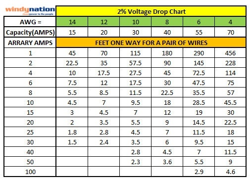
My panels have 14 AWG wire, which has plenty of capacity for the individual panels. But at 8 amps I’ll see a 2% voltage drop with only 4.5 feet of wire run. There’s one good reason for keeping those cable runs short. I used 12AWG for my extension cables to reduce the wire loss even though it’s not necessary for current carrying capacity.
So I have four panels feeding one MPPT controller connected to a 24 volt battery (two Tesla Model S modules in paralell) and two panels feeding the second controller. The four panel set delivers 15.5 amps at 80 volts (1240 watts) to the controller . The controller converts the voltage to 24 volts and therefore delivers 51.5 amps to the batteries (1240 watts/24V = 51.5 amps) disregarding any losses. We need 6 AWG to carry that current to the battery. Note that 6AWG wire at 50 amps has a two percent voltage drop in just 5.5 feet. Got to keep those wire runs short or invest in really heavy wire.
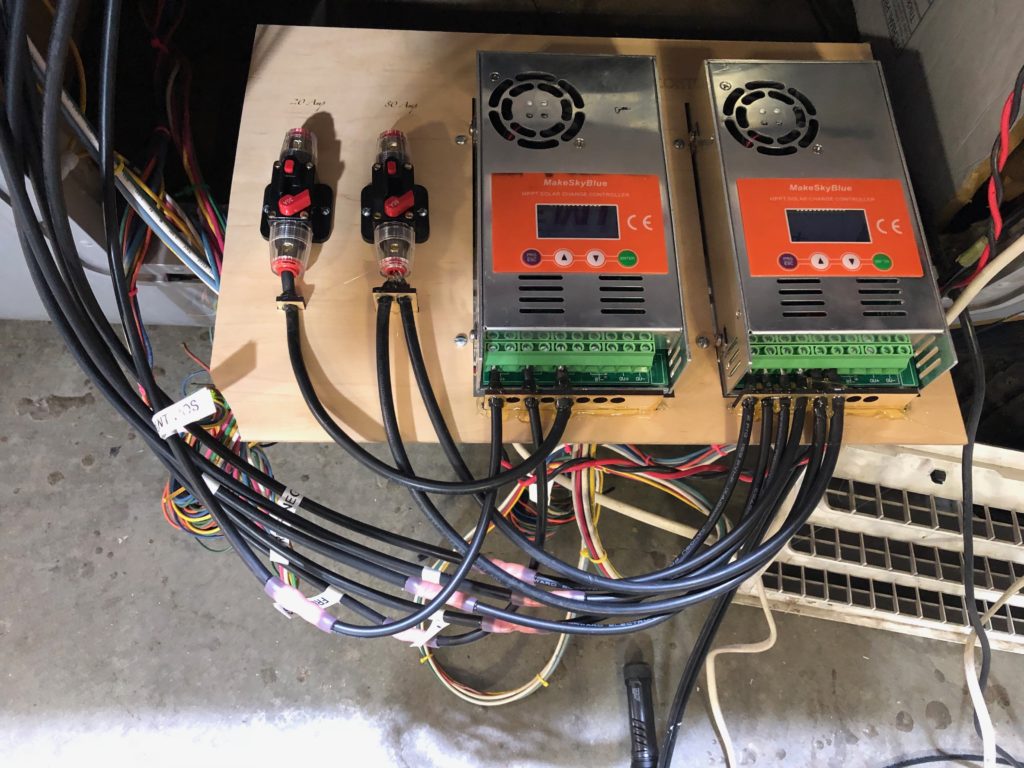
I’m using DC breakers for the controller to battery connection. One for each of the controllers and a fuse in series with the breakers, in part because I used cheap breakers for this low voltage, low current application, but any breaker is more likely to fail than a fuse–assuming the fuse is properly rated. I consider the breakers to be a convenience–if they trip you just reset them, and the fuses to be a necessity.
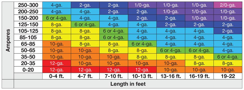
The battery to inverted connection is even uglier. My inverter is 6000 watt with peak watts or 18,000 watts for 20 seconds. The battery input to the inverter is 24 volts. sizing just for non-peak loads that’s 6000 watts/24 volts = 250 amps. That’s right off our little chart into /0 guage territory.
This chart doesn’t show voltage loss figures. The lengths listed are probably ten percent voltage loss numbers. I’ll be using 3/0 wire if I can keep the runs to less than ten feet, and 4/0 if I can’t.
Worse yet is the potential peak load, which is more important for fusing than for wire sizing. The most likely source of a high starting current is the air conditioner. The rated locked current load for my Mach 8 heat pump is 63 amps at 115 VAC. That’s 7245 watts, which translates to 302 amps at 24 VDC on the battery side of the inverter. It’s certainly possible to see that peak while other high-draw appliances are running, so I’d add another 100 amps to that figure to cover another 2400 watts of load, meaning I fused this wire with a 400 amp fuse.
There’s another more subtle issue though. One potential failure mode of the battery output is a dead short, or something close to it. A physical dead short on any lithium battery can generate HUGE current flows, and for the 11.2KWh of Tesla batteries I installed that could easily be several hundred thousand amps. Yes, I said several HUNDRED THOUSAND. The capability to interrupt that monster current flow is no trivial matter. I used type T fuses, which are rated to interrupt 20,000 amps of DC current (they are rated for 200,000 amps AC, but we already know this story). I could get specialty fuses like cars use, but they’d cost hundreds, maybe thousands of bucks, though I might be able to find some salvaged ones. But I opted to take a simpler road and pay 60 bucks apiece for Type T. A power systems engineer I spoke with said the rating of 20,000 amps is the capacity to interrupt without compromising the housing. He said I’d probably be fine even with a dead short, the silica sand in the fuse housing flashing into glass would shut off the current. But there would be some cleanup.
I’ve also considered adding an ultracapacitor bank to the inverter input to smooth out demand on the batteries and give the wiring a break. Some of these wackier ideas will probably wait until I need to solve an actual problem instead of just getting out in front of one that may never arise.
The next post will be about batteries and their management systems and I think I’ll be done unless people have other questions.


